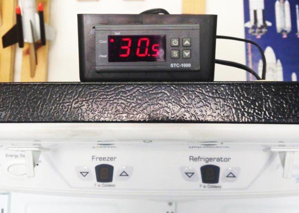
 Dave Juliano shares how to convert a refrigerator to a fermentation chamber without losing the freezer function.
Having an extra refrigerator is often a blessing to the home brewer – it can be converted to serve kegged beer, or to provide controlled fermentation temperatures to improve the quality of your beer. The one thing these two uses have in common is that, with few exceptions, the temperature range of a commercial refrigerator is too cold for the typical “kegerator” or “fermigerator”.
How Most Fermentation Chambers Work…
Several companies make plug-in thermostats to solve this problem, and the versions I’ve seen (Ronco and Johnson) all work in a similar fashion: the temp control unit plugs into the wall, the fridge (or freezer) plugs into the unit, and the thermometer probe portion of the unit is placed into the refrigerator compartment. Typically, the internal thermostat of the fridge (or freezer, we’ll just call them fridges for simplicity from here on) is set to its lowest point. When the external thermostat senses that the internal temperature is too warm, it energizes the control unit, which powers on the fridge. This allows the compressor to run, cooling the compartment.
Once the external thermostat senses that the temperature is correct, it de-energizes the control unit, effectively pulling the plug on the appliance. This means that if you open the door in this state, the light will not turn on. It also means that the freezer only runs when cold air is needed. Now is a good time to note that most modern refrigerators that have a freezer only chill the air in the freezer – if the fridge needs to cool down, the computer in the unit opens a damper and activates a fan that blows some of the cold air from the freezer into the fridge compartment.
The FERMigerator
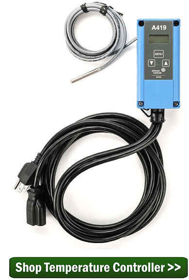 As you can probably see, using an external temp controller like this is easy, but compromises the use of your appliance. My plan to convert a refrigerator to a fermentation chamber enables the fridge to be set at a user-definable temperature while leaving the freezer unchanged. This way, excess food from the house can be kept frozen, hops can be stored, or the fridge can be put into service as an extra food-fridge if the need arises.
To do this, you will need the following supplies (Read through the instructions before going to collect anything, as you’ll need to make some measurements of your existing system before you buy some of the components):
- A temperature controller – Make sure to buy the model that suits your local power requirements, 110VAC for those of us in North America. These also may be available in Fahrenheit options, mine is in Celsius.
- A project box – These can be found at Radio Shack or an electronics shop. Get the temperature controller first, and then find a box that is about twice as deep.
- A regular duplex outlet – necessary if heating is desired (not covered in this article)
- An extension cord – to power the temperature controller, also not covered here
- A small piece of perfboard – from your local Radio Shack or electronics shop
- Two 1/4w resistors, the values of which will be determined below – electronics shop or Radio Shack
You’ll also need the following tools:
- An electric or cordless drill with a 1/4” bit
- Soldering iron
- Wire cutters
- A digital multimeter and knowledge of how to use it to measure resistance (don’t worry – it’s easy-peasy)
- Assorted hand tools to access the necessary bits of the fridge controller
The best place to start this project is to look up your particular model of fridge on an online appliance parts website. Look for the controlling circuitry for the fridge – this project will replace the factory thermistor with the new temperature controller. Be sure you’re looking at the right one! The freezer compartment will have the exact same device, but we want to leave that alone. The photos I’ve included are from a 2002 Amana French-door bottom freezer. When looking online, I could tell that the part I was after was housed in the control assembly at the top of the fridge compartment where the two doors meet. Once you’ve identified its location, unplug the fridge and begin carefully disassembling the trim around it to get to it, and then we’ll begin.
Steps To Convert A Refrigerator To A Fermentation Chamber
- Make sure the appliance is unplugged!
- Using wire cutters (if required — some thermistors are replaceable and may just have spade connectors holding them in) cut out the thermistor. Mine looked like a large white cylinder.
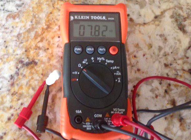 Using the multimeter set to read resistance (Ohms), connect the leads to each wire from the thermistor at room temperature.Here, mine is reading 7.82K Ohms at about 78°F. The temperature isn’t important – we just want to know that what the fridge computer reads from the thermistor is two states – hot and cold. Hot is any temperature above where we want to be. I brew ales and plan to lager, and saw no reason to ferment higher than this. If you’re doing something different, adjust the ambient temperature of this step accordingly!From this information, I know that when the fridge computer reads 7.82K Ohms, it will want to turn on to cool the fridge down.
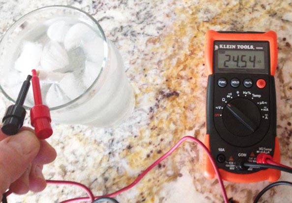 Keeping the multimeter set and the thermistor connected, now place the thermistor in a glass of ice water. This is 32°F, and represents the “cold” side of my needs. When the fridge computer reads 24.54K ohms, I know it will turn off.
- Now comes some math and a little knowledge of electronics. If 7.82K ohms equals “ON” and 24.54K ohms equals “OFF”, how do I trick the fridge computer into reading those?This is where the temperature controller comes into play. Unlike some other external temp controllers, this one is a relay (electronic switch). When it says to turn on, it closes a switch, which completes contacts. If those contacts happen to be wired to a 120VAC outlet, it will deliver 120VAC, just like the Ronco and Johnson units we discussed previously. If, however, we wire the relay to a couple of resistors, we can electrically trick the fridge computer into reading one of the two previously determined values, allowing the existing fridge computer and electronics to do the actual work of cooling the fridge down. Resistors, when wired in series, increase their resistance by the sum of the parts. In other words, if R1 and R2 are put end to end, R1+R2=Rtot. If they’re wired in parallel, however, we get the inverse: Rtot=(R1xR2)/(R1+R2). This is important because we need the fridge computer to read a higher resistance to turn off, and a lower resistance to turn on.
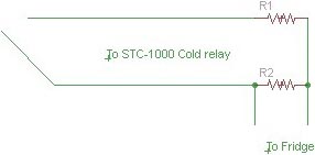 The STC-1000 will close the relay when the external probe reads a temperature above the set point, so when that relay closes, we want the fridge computer to read <8K ohms. When the temperature falls below the set point, the relay opens, so we want the fridge computer to read >24K ohmsI designed this simple schematic so that the fridge computer was reading R2 directly, and when the relay closed, R1 would be added to R2 in parallel, dropping the resistance read by the fridge, telling it to start to cool.
 - Here’s that math bit – how do we determine which values of resistor to use for this? Here’s how I did it. The values I measured weren’t standard resistor sizes, so I rounded.R2 must be 27K, since that’s the “Off” state, so to determine what value resistor I needed to give us 8K in the “On” state, I did math. There are websites that help with this, like this one. Type in the two known values (R2 and Rtot), and it tells us the value of R1 is 11.37K
_________________________________________________________
NOTES:
11.37K isn’t a standard size either, so I found 12K in my parts bin.
8000=(27000*X)/(27000+X)
Solve for X
X=11368,Or: (MATH+BEER+GOOGLE=RESULT)X=11.37K
Keep in mind the following things:
Always use the same units- 1k ohm = 1000ohms
Remember that the lower resistance is the “On” state, and the higher resistance is the “Off” state.
________________________________________________________ - Armed with these numbers, go to Radio Shack and buy some 12K and 27K resistors, and a small piece of Perfboard, wire, an enclosure, solder, iron, whatever you don’t have. The project from here is simple.
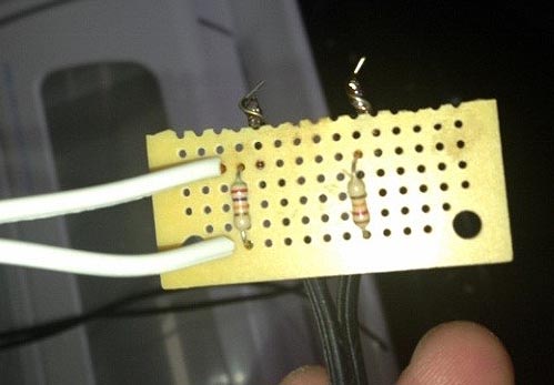 Assemble the perfboard. I soldered the two resistors to the perfboard, using their leads to make the connections, and also two pigtails of braided wire. The white wire was cut off of the end of the old thermistor, and the black is just some speaker wire I had that will connect to the temperature controller relay. Follow the schematic from above to ensure you have it wired correctly.
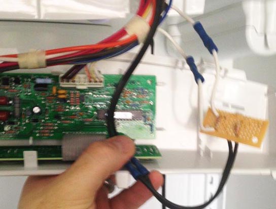 Wire it in: the white wires got crimped back in to where the thermistor was removed. The black wires got crimped onto the wires coming from the “Cold” relay on the STC-1000. Neither of these connections has a polarity to worry about. I had previously drilled a hole in the top of my fridge case by first making sure no refrigerant lines were in the way (check YouTube for lots of great videos on how to do this!).
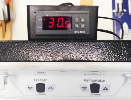 I tucked the bit of board and the wire into the shroud that holds the fridge electronics, and reinstalled the panels and covers. I did have to drill a small hole in the plastic shroud to allow the black wire from the temp controller out.
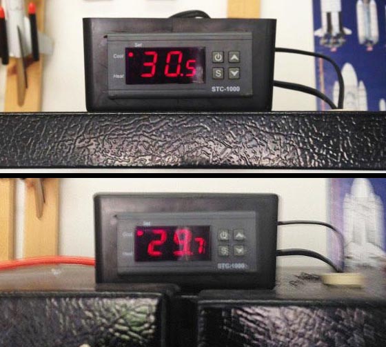 With everything plugged in and cooling, the STC-1000 is now in control of the fridge, while the factory-provided temperature circuitry was still in control of the freezer, and I could watch the temperature drop in the fridge! (Remember, this is Celsius, and in my garage in Tucson)
And that’s how you convert a refrigerator to a fermentation chamber or kegerator, and still use the freezer portion for storing hops or whatever else you need cold.
——————————————————————————————————————-
Dave Juliano is a DIY homebrewer and maintains a homebrew website detailing many of his projects.
